First, some good news: the mark 3/4 (I’ve lost track a bit) is done, and looks fairly identical to the mark 2. It has some nice internal differences, though. To start, it has a working accelerometer. This means that I can, in theory, implement a simple pedometer and sleep monitor. Unfortunately, all the howtos for that are not on the public internet, at least not that I’ve found yet.
I can think of a couple of ways to do it. The first approach I tried was to just count up a step when the g forces go over a certain threshold. To save you time: That doesn’t work.
The next thing I though of was doing bayesian analysis, saving the last few seconds of movement, and deciding with some logic if the numbers look like a step. This isn’t impossible, but I’m afraid it’d eat processor cycles and memory. If I ever get the phone app running, I can dump the data to a CSV and do visualization and patern mapping in ruby, which has nicer libraries for that sort of thing. Deriving them from first principal souds like a pain in the ass.
The other, simpler method, is to extend the first non-working method a bit: I also have a gyroscope, so I always know where down is; I could subtract the 1g of force that gives me, and then the spikes up and down should be really obvious. Also, it’s cheaper in the processing department. I’ll probably try that next.
Speaking of processing… I’ve just about outgrown the RFduino. I was going to use a shift register to make up for the lack of I/O, but there are a number of other problems with it:
- It’s close source. This isn’t a technical problem, but I don’t like it.
- Lack of compatibility; every library I use has to be modified, sometimes drastically.
- Size: it takes up a lot of board real estate, which means I can’t arrange things as I see fit.
There are two contenders to replace it: either an AVR like the ATMEGA1281, or a STM32F405RG underclocked and running micropython . It would be insanely cool to be running python. It’s enough of a hook that writing all the libraries over from scratch doesn’t seem so bad. But “Arduino compatible watch” also has a nice ring to it. There’s plenty of info to make designing either into the watch not bad, and I could then use an nRF8001 for the bluetooth. The chip cout stays roughly the same, but with a ton more flexibility.
Posted by Matt on 2014-11-03 06:43:51 +0000
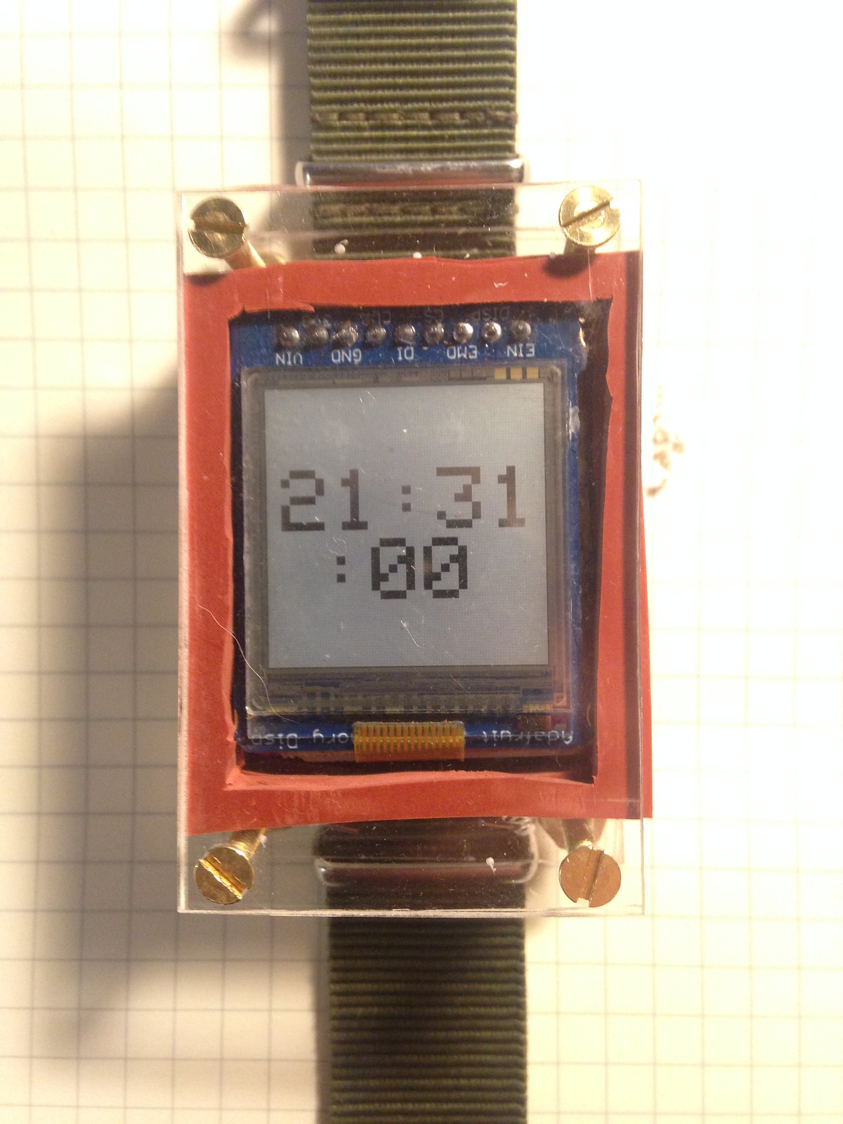
So, we’re on par for a status update a month. I’m OK with that. Version version 2.2 (major.board) is my daily watch now. It’s in pretty good shape, for a DIY watch. It’s not smart, not really, and that’s where I’ve got a ton of programming to do, still.
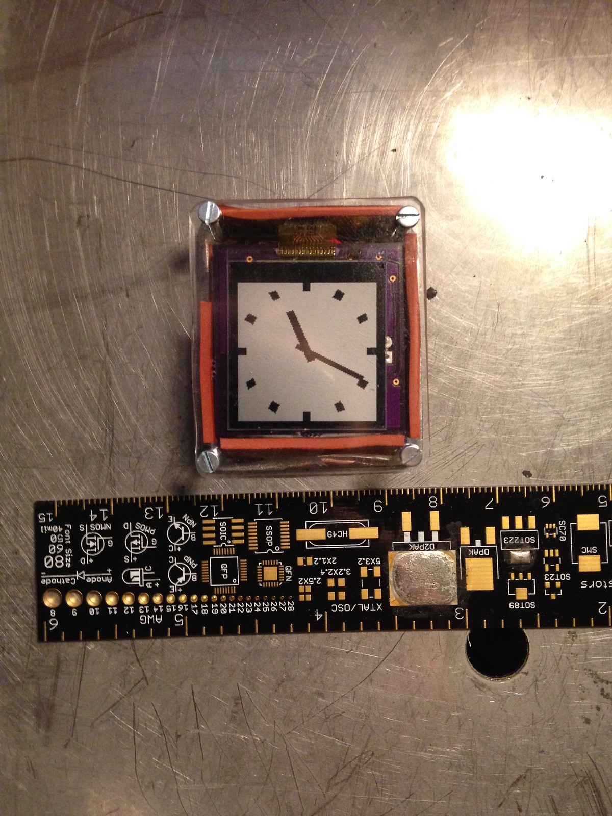
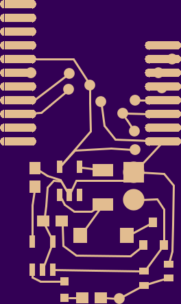
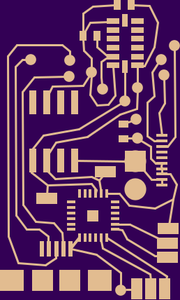
I’ve updated the ‘github’:http://github.com/mattmills/oswatch with a bunch of changes. First, the latest gerbers are there; the board is now very different. The new accelerometer is a LSM9DS0 , in a weird little package that turns out to be footprint compatible with QFN-24, the same as my shift register. The shift register has an interrupt pin that can send an intterrupt from any of the other pins when they change, so I’ve hooked up that, as well. Interrupts for everyone! The updated software also has some minor updates to the watchface, which now shows the day and date, and the markers no longer overlap the hands. I have a really convoluted ruby script for generating all the data to draw those rectangles; I didn’t want to think about doing floating point math in the machine.
I’m thinking for the next version, I’m also going to reduce the battery size again. 500mah is nice, but thinner is also nice, and charging isn’t really a hardship. Also, right now, it lasts more than 6 days; more than two days is fine. I might need a 3d-printer, to make a waterproof case. Making millimeter-accurate bends in sheetmetal isn’t easy, but a 3d-printed case would be able to do that, and have grooves for o-ring seals.
Posted by Matt on 2014-10-08 01:17:44 +0000
so, since I last updated here on the blog, a lot has been going on. I got the 2.1 revision of the board, single sided, and it had another couple errors in the power supply, and I discovered while hacking that I’d also ordered the wrong power regulators, 3v instead of 5v. So, I ordered another round of boards, this time re-reading all the datasheets and example circuts twice. I got it right.
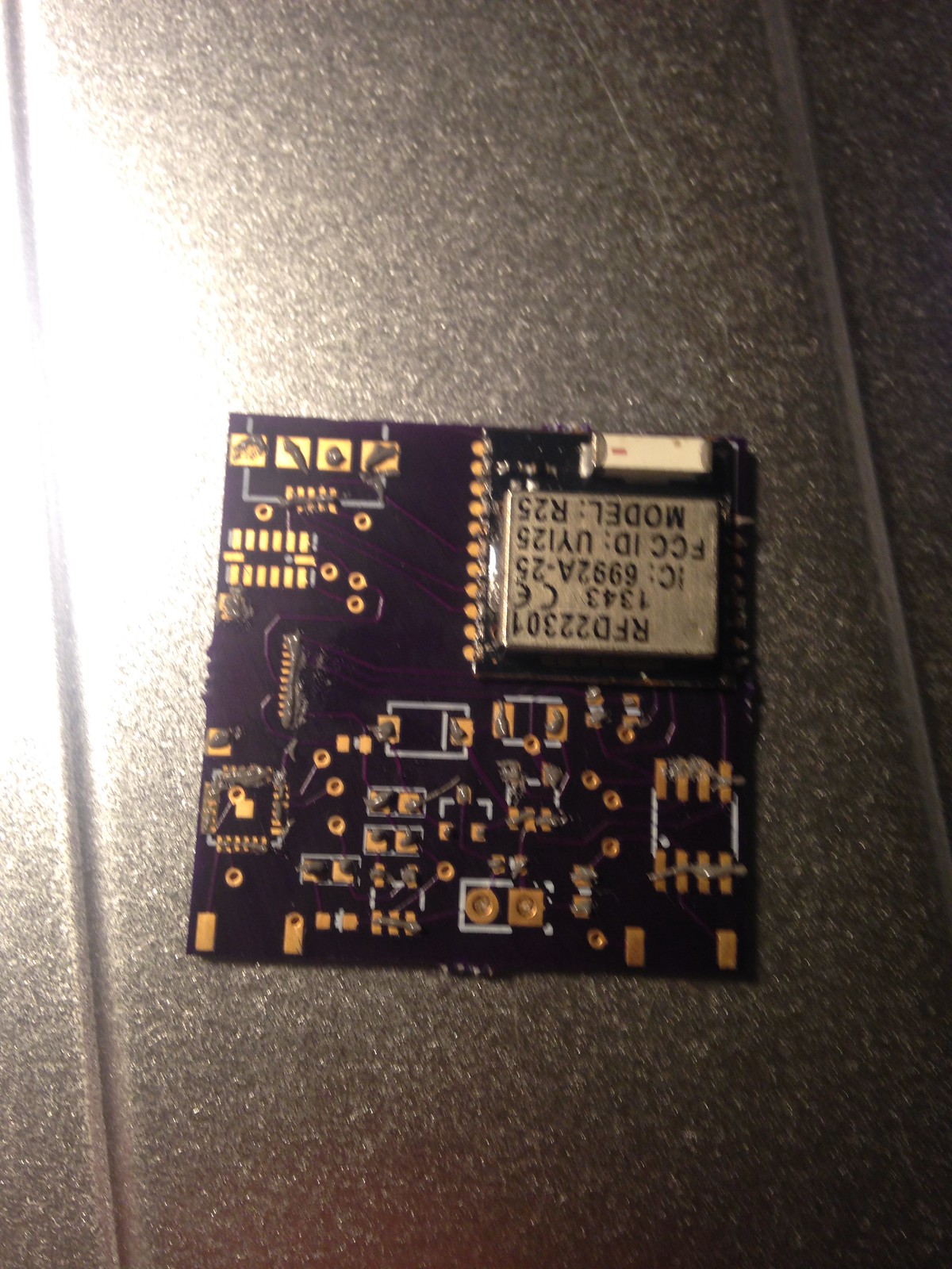
The circut board with hand-applied solder paste. Had to do a bit of cleanup on this one.
That said, the board still has some errata. The shift register isn’t properly configured, and so it eats power, and the accelerometer is also wrong in a couple ways. Also, the screen connector is too close to the edge of the board. I’m working on these defects and some improvements; LED lights for the screen side of the board, to serve as backlights, a different accelerometer altogether, and maybe a vibration motor, for notfications.
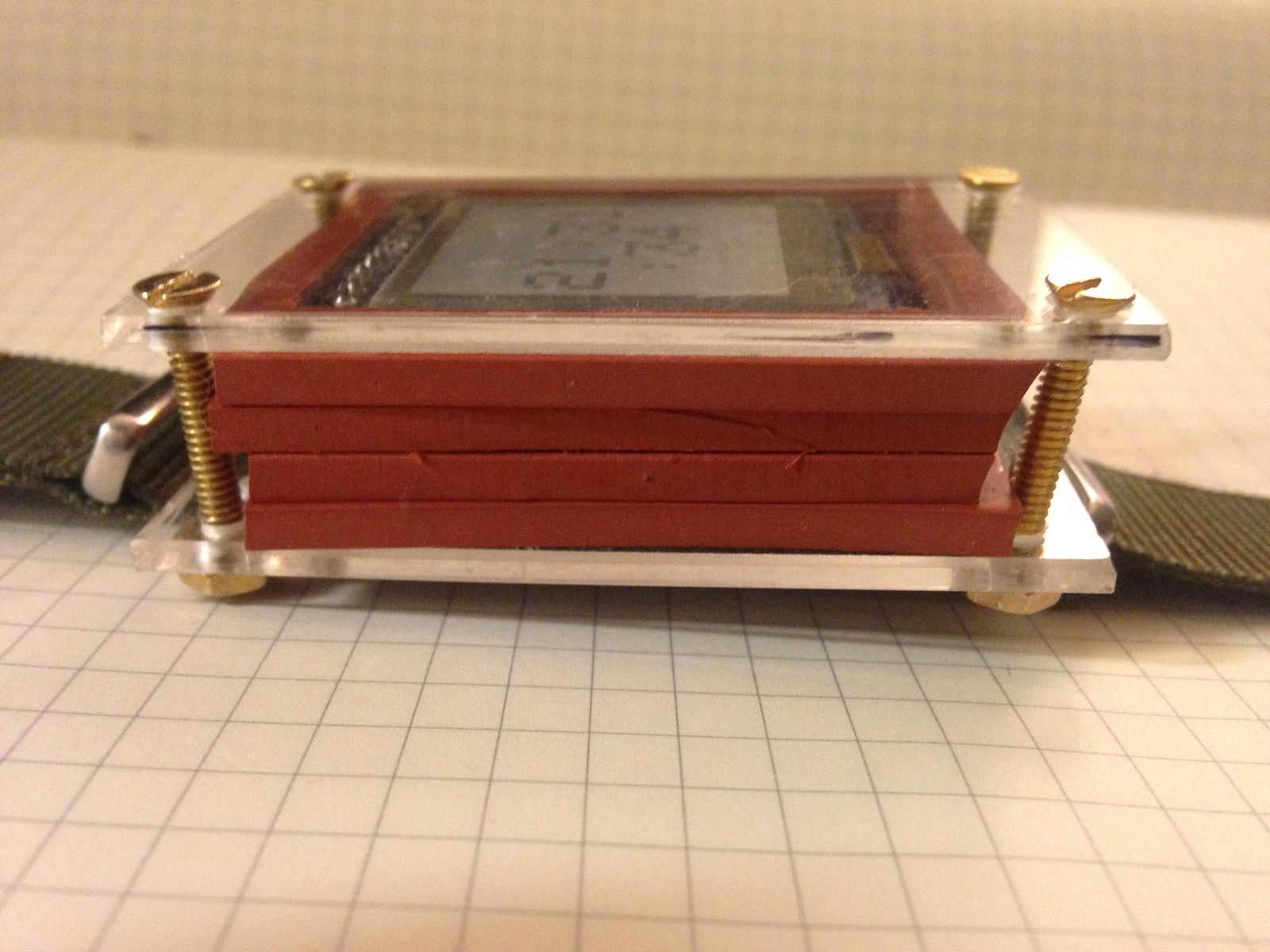
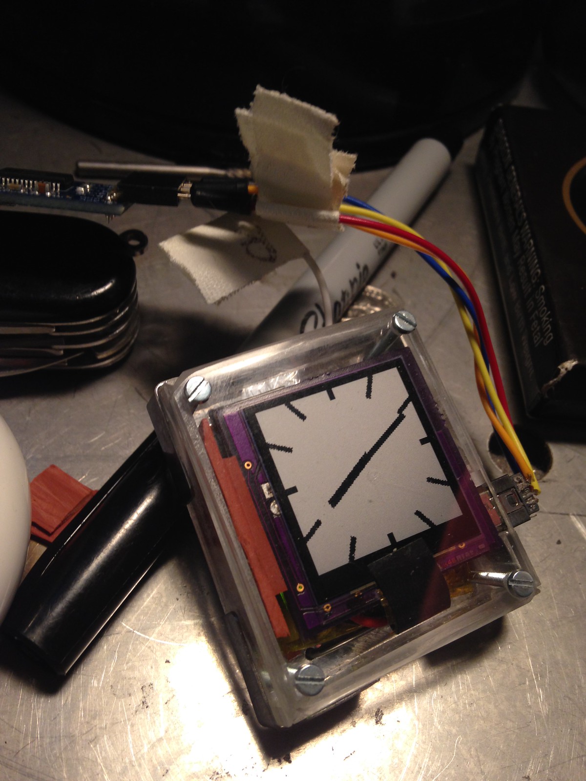
Exploded v2.2, before I’d build the first enclosure. The ribbon cable on the display is super delicate; I’ve reinforced mine with tape.
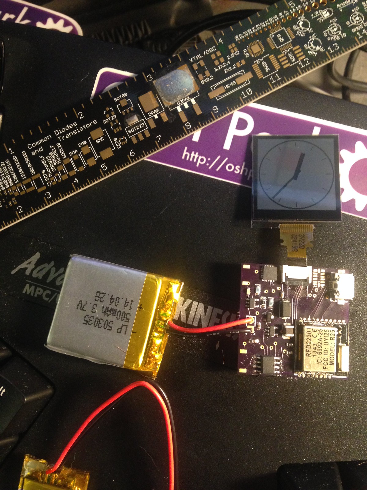
I have managed to make a much smaller, fuller featured version than the old one. The current version uses the real time clock, has a 3x larger battery, and is 5mm thinner. I’ve removed the shift register, and the whole thing is on track to run through wednesday evening, having been last fully charged on saturday at 6pm. If I’m a little lucky, it’ll run through thursday morning.
Case #4, with rubber sides. I wasn’t a huge fan of the rubber, so…
On the software front, I’ve written a new analog watchface, with rectangular hands instead of lines, and nicer hour markers. As I mentioned above, I got the RTC working with this board release, so now I shouldn’t have to reset it every morning, assuming I don’t let the battery die all the way. I’m to the point where I need to take an inventory of the parts on hand; I have a probably 2/3rds of the next watch here already, just a few leftovers to pick up (a couple more sharp LCDs, maybe another extra rfduino).
Case #5, with plexiglass on 5 sides. It’s a little chunkier, but not bad. Stainless steel back, and corners for strength.
I think that’s all for now. Keep an eye on the twitter for more frequent updates.
Posted by Matt on 2014-09-16 05:00:59 +0000
So, currently, the project is a bit all over the place, with a lot of things happening all at once. I’m hopeful that by writing them all down, I can get some sleep. edit: totally worked!
First things first: the board design I was so happy about turned out to be unworkable, mostly because the battery was backwards on the schematic, so I connected a bunch of stuff to ground that shouldn’t have been. I reworked it, but I’m holding off on publishing a revision until I know it works this time. The new version is larger, taking up the full area of the screen, roughly. It’s also one-sided; the bottom of the board only has some traces. This will make it thinner overall, so that’s a bonus.
While I’m waiting for that to come in, I’ve been thinking about what constitutes ‘done’ for this watch. I’d like to do one more prototype, at least, with a backlight and a more sophisiticated accelerometer. I’m hopeful that the real time clock will let me actually put the watch in low power mode between updates, and save battery. So ‘done’ for me is dark readable, waterproof, no dissassembly to upload new firmware. Battery life somewhere in the range of 5-7 days, which I may have to acheive with a larger battery.
Case design is another area that needs some work. I’m thinking in a lot of directions here, and there are some interesting engineering limitations. RF and metal cases don’t go well together, but I may test using metal anyway, to see what kind of attenuation I get. The face will be open and nonconductive, at least. I’d also like to do a women’s version, but it’ll have to be a two-sided, four-layer board. I have no idea what I’d use for a display; I’d want something roughly 1/3rd the size of what I’m doing now. It’s different enough that it should probably be shelved in favor of getting something done. Maybe size isn’t even an issue, and it’s just style.
A word about solder paste and tiny packages with pins hidden under the chip: use less. That said, you can hand solder 0.5mm traces, using the methods in this video. My first pass with the reflow oven, I had a ton of solder bridges; I used too much solder, and I was a little sloppy putting it on. So, don’t do that. Syringes seem like a good idea, but really, the toothpick method works really well; I used a needle, and it gives pretty good control of where paste goes and how much you apply.
The other thing I’ve learned is about supplies: the adage “If you need one, order 10” is completely true for small components. I’ve been wrong about a lot of things, including the number of resistors and capacitors I needed. 0401 parts are tiny, and I’ve also lost at least one of them. I damaged one ZIF connector as well. So: always order extra. I’d say order ten of anything that costs less than a dollar, or is smaller than 2mm^2.
That’s all for now. The new boards arrive tomorrow, so look for a post on tuesday with photos and hopefully a new, working prototype.
Posted by Matt on 2014-08-11 06:42:21 +0000
So: I totally stole the idea for this thing from all over the place. There are dozens of tutorials about how to build a reflow oven with a toaster oven. By far the coolest is the Halogen Lamp reflow with low-temp solder paste, but assuming you only have regular paste, what I’ve done will also work. Note: I’m moving to the low temp stuff for future builds because it’s faster and easier to work with.
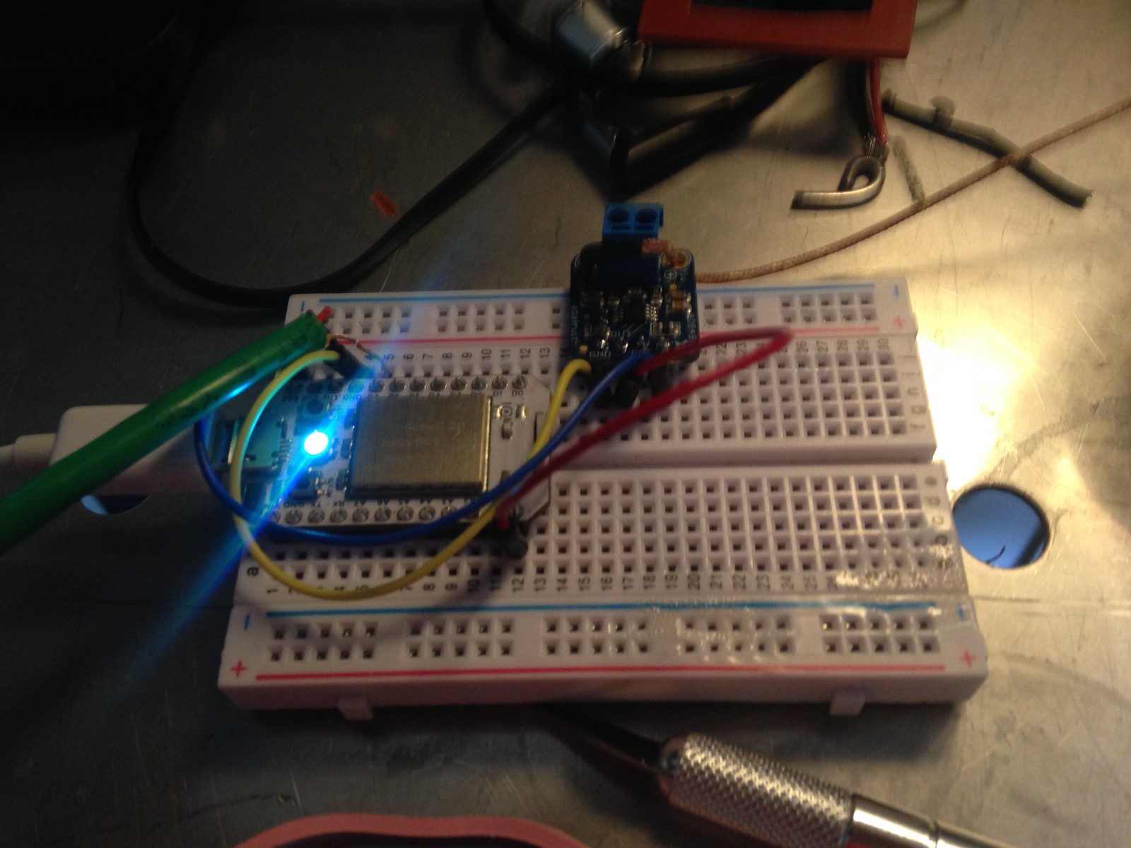
The breadboard all wired up. The big green phone wire is running to the power relay.
First, supplies: You’ll need a toaster oven. I ordered one from the big river , but anything that’s functioning and has both top and bottom elements should work just fine. Don’t use it for food afterwards; not only is the metal in solder toxic, but the fumes from the flux are also not great. There’s probably an MSDS around somewhere, possibly from wherever you can buy solder paste, that describes the precautions you should take.
Second, you’ll need some way of measuring the temperature inside the oven accurately. I got a thermocouple and an amp from adafruit, but you could also hack a kitchen thermometer. They’re less accurate, but cheaper. I went for accuracy here.
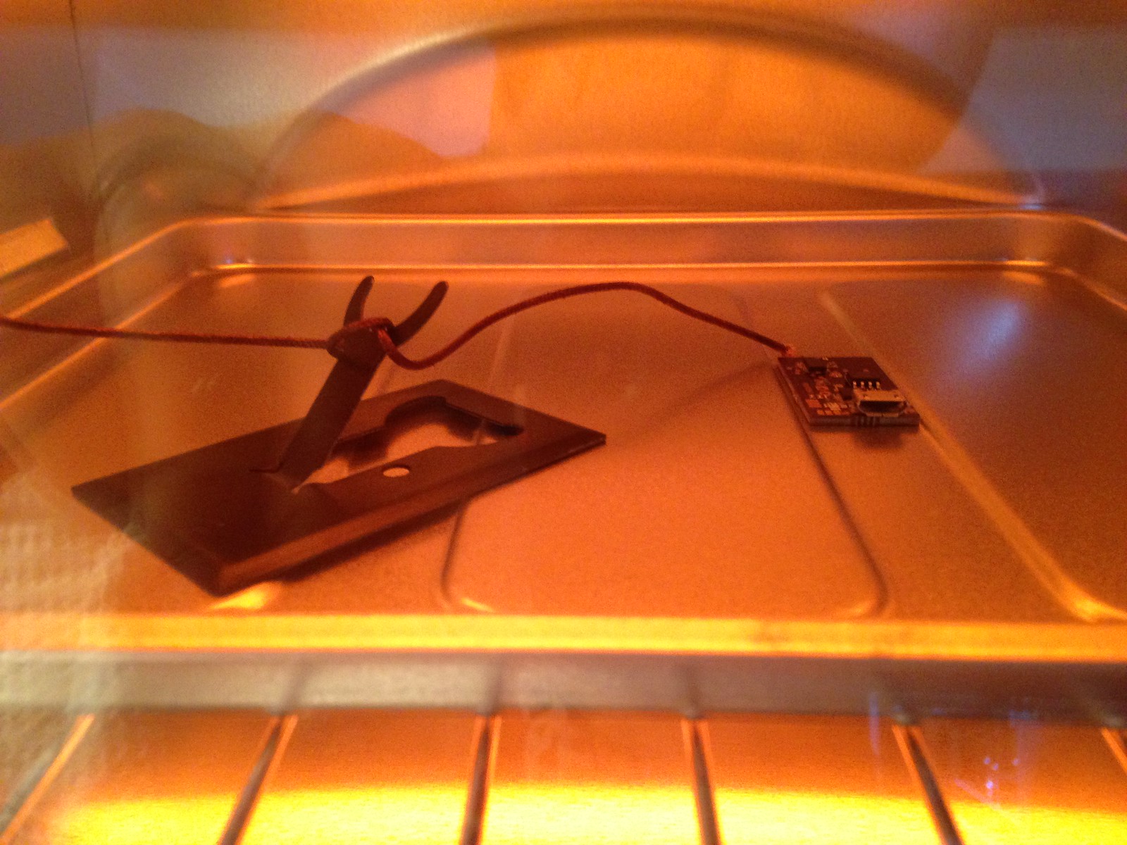
Oven in use.
Third, you’ll need some way of turning the power off and on. Some people have observed that toaster ovens have perfectly good knobs on the front, and you can get away with just turning it off and on that way. I’m lazy, and I have a short attention span, so I got a powerswitch tail. It’s a pretty nifty isolated relay; it connects to a digital pin, and when you bring it high, it turns on the power.
Lastly, you’ll need a microcontroller of some sort. I used a Spark core, because it was on hand and easy to program. I didn’t even change the firmware. I used the tinker firmware and some ruby code to talk to the spark API. I could have used a raspberry pi, an arduino, whatever; the requirements for this project are super minimal. Really, you need about one-second resolution on the thermocouple, and the same on the power. My code is here: https://gist.github.com/mattmills/746bc1e8fed75ea413ae (note that I’ve taken out my access tokens). Note that the values for temperature are probably unique to my oven and room temperature; if you make one of these, definitely do a test run.

A finished board. There were a few bridges, but this was the first effort.
Assembly: I didn’t even bother with a permanent board. The Spark core is dead useful, and I don’t want it tied up in one device. I stuck it in a breadboard, wired up the amp to power and an analog pin. Wired the powertail’s control lines to a digital pin and ground, and plugged everything in. I ran the code once, tuned when to stop heating for both stages, and then ran it again. The curve was in the bounds of workable, so I put in a test board, and it worked :)
Posted by Matt on 2014-08-11 02:43:08 +0000
So, after many weeks slaving at the computer every night, I’ve managed to produce a circut board design for v2 of the watch. The design is a little rough around the edges, but I think it’s worth walking through things at this point. First, some general considerations: I decided not to give a shit about cost per component in this design. I’m working with a lot of other constraints, mainly board speace, my time, and my ignorance. So almost all of these components are things that I’ve seen used in kits, things that are dead simple, and usually the smallest available version. Where possible, I’ll link to resources that have helped me along the way. The software that I ended up using was the one with the easiest learning curve, Fritzing . The biggest drawback is that it can only do 2-layer boards. I could probably make the board 20% smaller with a four layer design, but I’m unwilling to pay for eagle, and KiCAD was impossible to install when I was trying. I did later get a binary version to work, but the drag-and-drop simplicity of Fritzing sold me.
The heart of this board is the RFduino, a mostly Arduino compatible ARM M0 system-on-chip with 7 GPIOs that runs at 3V. It was chosen for it’s size and ease of programming; there are a ton of libs and code that work out of the box for it. Also, it’s very small; smaller than a microduino, and has blutooth built in. It was suggested to me by my friend @mojinations . Originally, I was going to do something very similar to the OSWatch, just build the Amtel and the bluetooth into the same board. When I found the RFduino, I knew it was the right part, just based on size alone. The drawback being that it’s SMT only, which has made prototyping interesting, to say the least. Also, it only exposes 7 of the processor’s available 30-some GPIOs. I understand there’s a space constraint, but it would still be nice to have a few more (not to mention reducing my part count and complexity even further).
Moving on to power, I’m using a lipo battery like this one from Adafruit. This feeds a Maxim MAX1724EZK30 regulator, which was chosen for its very low quiescent current, although it was a bit more costly than other switching regulators.The board also will charge the battery over USB. It uses a MCP73831 charging IC and a power sharing circut described here ; basically it uses a MOSFET transistor to switch to the USB power when it’s connected. As an aside, I found that page looking at photos of other people’s DIY watches. His is pretty rad.
Next is the screen. Sharp makes a family of low-power memory displays, which are like e-paper, but with fast refresh rates. I decided to build around one of these instead of a more typical OLED because I always want the display to be on, telling the time. If a watch is about displaying essential information, it shouldn’t need a button press to see it. I got the idea from the Adafruit breakout board, which isessentially a level shifter and a voltage regulator hooked directly to the screen. There are actually two displays that are interchangeable here; one 96×96 and one 128×128. They’re physically about 1mm different, and the connector is the same. Unfortunately, they’re also backordered everywhere; I’ve been forced to buy breakout boards to get the part.
On the I2C bus, we have three chips. First there’s an accelerometer, which I have no idea if it’s the right one, but it’s at least widely supported. This will allow the watch to do activity tracking and shake gestures. Second is the real time clock. I went with the Maxim DS3231MZ+, which has an internal oscillator, so reduces the BOM by 1 part. I could probably get away without a RTC, I mean, my current version doesn’t have one. That said, it’s pretty essential that the watch keep time. Last on the I2C bus is a I/O expander, which has 4 pads exposed for buttons, and another two for shits and giggles. I should probably make the extra two pads the I2C bus.
The full BOM is in this google doc . There are some various capacitors, resistors, and such that do things like power conditioning, pullups, or config. Nothing super crazy. The full set of gerbers is in the github repo, along with the code I’m currently using. Astute readers will note that none of the new hardware is implemented at all yet. It’s on my todo list, as soon as I build it.
Posted by Matt on 2014-07-10 15:58:50 +0000
So, I’ve made like three cases so far, “case” being the lingo for the container a watch goes in. I don’t have a 3D printer or a machine shop, so I’m limited to what I can hand fabricate. That said, I have a long history making things with my hands, and I’ve been able to make a couple different things, the last of which is actually not that bad.
The first one was metal, which was ok, except I was holding the circut boards in with tape, and metal blocks radio signals. Not ideal, but for the time that I was just wearing it as a timepiece, it was ok. The band was attached with wires looped through holes; imagine a staple, wrapping around the band and through the metal.
The next case was all acrylic; I had the idea to make a laminate case by cutting the inside holes with a dremel; this turned out to be way too much work. Acrylic kind of sucks as a material for fine work. You can cut arbitrary streight lines pretty easily, so I made a bunch of rectangles, and made that into a box with some superglue. One side I left open, with a bit of the two sides sticking out, and cut grooves so I could make a slide-in cover out of aluminum. I noticed after wearing it for a bit that it had super sharp corners, so I sanded all the edges so they don’t gouge random people on the bart (or my wife).
Then, of course, I broke that. I was trying to drill holes for buttons, and the top came off. So, instead of trying to fix it, I went back to the drawing board, and thought for a little while, and came up with my favorite so far. A laminate design like the second case, but instead of using acrylic for the middle sections, I used gasket material, which is cuttable with an X-acto knife. The top and bottom are acrylic, and it’s held together by the four bolts you see in the picture.
I could continue to work on little stuff like this indefinitely, but to make new features, I need to add to the circuts, which has become inpossible on the perf board. It’s overworked and out of room. I’m calling a halt to development on this iteration, and focusing on the schematic and board for the next major version.
Posted by Matt on 2014-07-03 05:41:19 +0000
So, with the watch assembled and largely working, work on it slowed a bit. I didn’t want to break it. I added some buttons, that didn’t do much, and left it, stable, for a week or so. I worked on the schematic for version 2.0, a.k.a. the DVT. I routed the copper for most of it, too; I have some things left to add. Using I2C for a lot of things, since there are only 7 I/O pins on the RFduino, and I’m still one pin short. There are tools for that, at least.
Speaking of I/O, buttons! In order to get things working, I couldn’t just hook up one side of the switch to 3v and the other to the digital pin. That would be too easy. There are a lot of factors in play here. This is worth a little diversion. I come from software, where by comparison we live in a world of platonic ideals, where 1 always equals 1. Hardware is harder. For starters, the digital pins don’t read 0v when in their natural state. You have to use either a pullup or a pulldown resistor to get a 1 or a 0.
Then, interrupts, oy! Somewhere in the libraries I’m using, there’s some interrupt driven thing that was causing the watch to freeze randomly after pressing the button. Not all the time, but probably 1 time in 10. I wrapped my whole loop function in noInterrupt() to fix it. The code is on github here: https://github.com/mattmills/oswatch . It will probably change a lot while I’m adding features and improvements.
Next up, hopefully in the next couple weeks, I’ll have the DVT schematic and gerbers. There’s not a ton left to do, basically wiring in the screen and accelerometer, and maybe a RTC if there’s room. 8 mil traces are tiny, but I’m leaving basically half the case for battery. The original plan was for a 35×35mm final board, and I’ve got that down to 35×18mm, which will make the whole watch thinner and more wearable. I’ll also post the Fritzing files, which may be of use if anybody wants to roll their own hardware. It’s limited to a 2 layer board, which kinda sucks, but it’s doable.
That’s all for now. More news when there’s more to report.
Posted by Matt on 2014-06-30 01:05:49 +0000