So, it’s been a while since I bothered to document anything, but if you’ve been following the git repo, you’d know that the work continues apace. v5 has come and gone; I made substantial changes to the layout, built a version with working pushbuttons, and wore it for a while there. Then, life caught up with me and I didn’t work on anything fun for a while, but now I’m back at it.
One day, while I was contemplating if I should add yet another feature, I thought that it really sucks that to add any features I have to change the board layout, wait two weeks for a board, and then see if what I’ve done actually works. Then I thought, why don’t I just break out a bunch of GPIOs and make Ourglass like a dev kit? That’s how v6 was born.
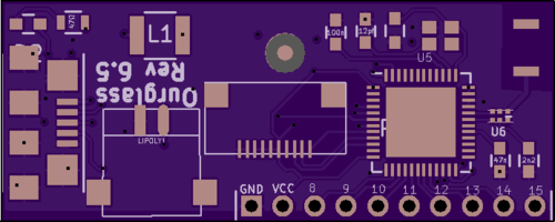
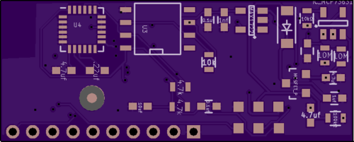
I’ve shared the new boards on OSHpark for the curious. Version 5 was an incremental improvement on 4, but rebuilt from scratch. All of the parts were moved around, and some features with interrupts were added. Version 6 is based on version 5, but the l-shape has been changed to a rectangle, the expansion header added, and now the design is double sided.
The sharp-eyed may notice a few other things: there are test points and fiducials on this version. Version 6.5 is the first pass at making Ourglass production ready. I’d like to produce somewhere between 200-1000 boards, which seems to be a sweet spot for this kind of run. If I’m selling just the board (no battery, no screen, and no case) they’d cost about $60 in that quantity (to buy; manufacturing cost is about half that). With battery, case, and screen, it’s more like $100. This would have to be a limited run, since to make a real commercial product I’d also have to have FCC certification. I could see doing 1000 at a time, though. Crowdsupply or Massdrop, with a laminate case, similar to the early prototypes. Notably, you can get silicone laser cut to spec; I think that would be really interesting.
Also a part of the work of getting to a product: Getting the software toolchain up and running. Out of the blue, around the beginning of December, someone from the Apache Mynewt project reached out to me. They have a fully open-source RTOS based on the NRF51/52 including bluetooth stack. There’s no compatibility with Arduino, which was a goal of mine, but I think there are two ways to go with that: either write a bunch of tutorials for working with MyNewt in the openocd toolchain, or figure out what’s needed to build a compatibility layer. I think both are doable.
In an ideal world, you’d be able to upload a program over USB or BTLE from the Arduino IDE; this lowers the bar for beginner-level entry. Then, for advanced users, the source for the whole stack is available, and it can be programmed over SWD. My bet is that most users will want to tweak a little, and some people will want to build a whole interface from the ground up. I want Ourglass to be a platform that enables that kind of experimentation.
Posted by Matt on 2017-01-23 19:09:36 +0000
This post is part of what I hope to be a series that will de-mystify and put in one place all the things I’ve learned constructing these things, and at the same time lay out the steps to building a working version of the watch as it is now. First, we’re going to talk about tools, and then I’ll lay out the current BOM, and how to go about getting some of the parts and material that are hard to find.
note: I don’t get any referral money from any of my links; wherever possible, I link to where I got something, or a known reputable source. A lot of these links will be to Adafruit, because they have all the best stuff.
The difference between a good tool and bad tool is measured in the hours of frustration the bad one will cause you. Yes, you can accomplish a lot with minimal tooling, and the good stuff doesn’t have to cost a lot. For example: this pair of tweezers is really very good, and very reasonable at less than $4. So, the list, with some annotations:
-
Soldering Iron – Why would you need one of these for a surface mount project? There are four through hole joints to be made, but you’d need it anyway, to clean up the inevitable bridges.
-
Solder wire – For the through hole joints. If you’re in the EU, you’ll want the lead free ROHS compliant stuff: here.
-
Solder Paste – This stuff is kinda amazing. It’s a low-temp solder paste that makes SMT work a lot easier to control. Instead of a precise reflow curve to avoid damaging components, you just heat till it’s all liquid, wait ten seconds, and turn off the heat. If that link dies, search digikey for “SMTLTLFP”. It’s also ROHS compliant!
-
No clean Paste Flux – Another thing that’s cheap and handy to have around. It helps solder flow onto a joint, or onto your solder wick.
-
Solder Wick – This is a braid of fine copper wires which wicks away solder when you heat both at the same time. You can remove excess solder, or even desolder some components with it.
-
Tweezers – I actually have two of these on hand, because I don’t want to do without them if I mislay them somewhere in the junk pile that is my desk. You’ll use them for placing all of the components, removing stray hairs from the board, plucking hot components from molten solder (don’t worry, we’ll get there).
-
Soldering Iron Stand – Nobody ever told me how great these were, so I’m telling you. A stable place to put your iron while it’s hot is essential. Note: Sometimes the spring on the inside will pop off; just push it back on. It’s safe to use that way, but not as stable as having both springs.
-
Hot Air Rework Station – This is probably the only really big ticket item on the list. You might be able to do without it, but remember what I said about frustration?
-
Halogen lamp – This is what is going to heat the whole board up for reflow. Note that the Home Depot is bad at online ordering; you’re better off going to a store. Any single bulb, 500w lamp should do the trick. SAFETY WARNING: hot lamp is hot all over, except maybe on the handle and base. It will set fire to things that touch it, so use caution.
-
Programmer – You can also use an arduino with the chip pulled, both methods are very similar.
-
Wire Snips – Another item I did without for years, a good pair of flush cutters. Their usefulness can’t be overstated.
Parts
Now that we’ve talked about the specific tools, there are a few parts that are peculiar to this BOM that can’t just be stuck in a spreadsheet.
-
The PCB – This link is to v4.4, which will soon be replaced by 4.5. That said, 4.4 is fully functional, but the screen folds the wrong way. I'm fairly sure it'll fit in the case still (target was < 4mm). I'll update the link when it's there. 4.5 is there! New balun, fixed screen connector. OSHpark is the best, and given the size of these traces, I wouldn’t recommend any of the cheaper options for PCB fab.
-
The paste stencil – Not required, but without a stencil, putting paste down takes about half an hour. With it, it takes about a minute. You’ll have to grab the cream layer from the Github Repo and upload it yourself, since oshstencils doesn’t have shared projects.
-
Battery – These are often out of stock, I don’t know why. There’s a 110mah version that you could also use.
-
Case – No link, because this is one of the places the ‘Y’ in DIY happens. Also, my case designs are rubbish, and I don’t have any for the v4 series movement. I’ll probably post an STL when we get to that phase of the howto.
-
RFduino – This is the brains of the operation. To get the chip with a bootloader, you’ll need to buy one of these and desolder the RF sheilding, and then desolder the chip itself. This is where you’ll be glad you got the hot air station, or borrowed a friend’s. You may be able to hear up the RFduino on the halogen light to desolder it; it’s worth a try. After desoldering, you usually have to clean some solder off the center pad with solder wick.
The rest of the BOM is here, but some of the links are stale. I last updated that for version 4.1, and we’re at 4.4. The BOM is pretty stable at this point; I don’t see changing it much.
And that’s it! probably a $200 investment, if you can borrow a hot air station, or more like $300 with it. Order 10 or more of the components that cost less than a dollar, since they’re cheaper that way, and you’ll need extra.
Posted by Matt on 2015-10-15 05:19:52 +0000
Blogger’s note: I wrote this shortly after coming back from magmaconf, and then forgot about it. Oops.
This last week I’ve been in Mexico, giving a talk at Magmaconf . The conf was awesome. I genuinely enjoyed all the talks I saw, and was sorry to miss the ones that I was in the pool or at the beach for. There were two other hardware talks, and I got a lot of compliments on mine; The guys from Hybrid Group, especially Ron, got everyone hyped up about the hardware future, and then I came in later that morning and showed everyone how to get started making that future.
Here’s the genius of the conf: the pool/beach are really the hallway track, but with beers and relaxation. Sun, heat, cool off in a pool, wade into the ocean. You might be thinking “That sounds like a recipe for some harassment nightmare,” but no, they have a strict anti-harrasment code of conduct, posted right on the home page. Very cool, and AFAIK there were no issues.
Anyway, the v4 work continues apace. I assembled a rev0 board and discovered some errata. The footprint I made for the quartz crystal was wrong, and there was also schematic error. I had the wrong part number, and so was wiring the power regulator wrong. Rev1 is at the fabricators now, and it should be done maybe a week from friday? I also put up a github repo: mattmills/ourglass that has the schematics and code that I’m currently using. It’s missing all the older iterations, but that’s not a huge loss. Anyway, it’s 2am and I’ve been up far too long.
Also notable: After four revisions, I finally have a decent handle on version 4. I may do a fifth, but the fourth is working. The screen didn’t work for the first three, but that’s because I reversed the order of the pins on the screen connector part. Yr. hmbl-er blogger.
Posted by Matt on 2015-06-22 06:50:15 +0000
So, I changed my mind again. I was about 2/3 of the way through breadboarding the fourth version of the watch circuitry, and I decided I didn’t want to build a SPI bus with multiple slaves. That, and 8mhz was really too slow. So, I went back, and re-designed with the NRF51822. It’s a fine chip, and somewhat reduces my part count.
I’ve sent the board version off to the fab, but not much else has changed. I’m going to desolder the NRF from one of my RFduinos, to skip building a bootloader for now. It’s a pretty simple matter, but there aren’t any open source examples that I can find, and so I’m taking the easy route. If I ever produce more than one of these at a time, I’ll build a bootloader from scratch, and try to make it as open as possible. The softdevice that runs the radio is a blob, which is unfortunate, but there’s nothing I can really do about that, unless I end up making tens of thousands of these things, and can hire someone to build an open version. I’ve looked around for alternative ARM M0 chips with bluetooth, and there aren’t that many. NXP makes this one , but it also has a blob for the BT stack. There is an open-ish bootloader for it, in active development, but there isn’t really any reason to switch at the moment. I’m sort of thinking the next version will have wifi, but the power requirements for that are nuts.
Things I need to write about: Using KiCad, from schematic to board. It’s actually not that bad, once you figure out a few things. Also, design considerations for manufacture, which I’ve mostly been ignoring. Through hole components are bad, and dense packing is bad. I don’t have any ground planes in the current board, which means that I’ll probably have weird intermittent faults, if it works at all.
Posted by Matt on 2015-05-12 04:49:27 +0000
TL;DR- use the labeled hardware SPI pins and AVRdude, and life is good.
This is a tale of woe, of how I tore apart a day’s work trying to get to the bottom of something, and then solved it sitting at the bar waiting for trivia to start. Basically, I have some stuff on hand to build a breadboard version of the v4 Ourglass. I need to do this to validate my circut design, as well as measure some things about power consumption and timing (see previous post). There are a bunch of resources on how to build a “boarduino” online, but a couple of my parameters are out of the ordinary, and threw me off.
First, I’m using an Arduino Micro , which isn’t like all the other Arduino boards. The hardware SPI is on the ICSP header. So, the setup is something like:
| Arduino Micro |
|
→ |
|
1284p (pin numbers) |
| MOSI |
|
→ |
|
6 |
| MISO |
|
→ |
|
7 |
| SCK |
|
→ |
|
8 |
| D10 (reset) |
|
→ |
|
9 |
You also need to connect the VCC, both GND pins, and AVCC; those are well known, and left as an exercise for the reader (seriously, consult the data sheet). Once everything is hooked up, you’ll need to decide how to set the fuses. I used this online fuse calculator (edit: be careful, and read around about how to set your fuses properly, I’ve bricked my chip since getting it to work by messing around). There are probably others, and of course, you can just stare at the data sheet and figure out 3 bytes yourself. I’m using the internal oscillator, and setting the brownout to 2.7 (since I’m running at 8mhz and 3v). In reality, I could probably disable this altogether, since the battery I’m using has a pretty sharp cuttoff, but it’s strongly reccomended here to leave it on if you’re using a bootloader at all (also covered more in depth here).
I picked a bootloader mostly at random, from this post about bootloading the 1284p (using an uno, which lead me to waste half a day). I may regret this; I haven’t verified that it works, but avrdude reported success loading it onto the chip at least. Edit: still waiting on the final verdict, as I need an external oscillator for serial communication.
So, in the Arduino IDE, there’s an example sketch called ArduinoISP. You’ll need to change the line “#define RESET SS” to be “#define RESET 10”. Then load it onto your micro, and you should be able to use avrdude to load your fuse configuration and bootloader. You can also use the IDE, although I haven’t tested that; you need add the hardware descriptions to your personal ~/Documents/Arduino/hardware/ (on mac) and restart the IDE to get the board type. This will also set the fuses based on what’s in the boards.txt, so make sure that reflects what you want.
Of course, since getting this more or less working, I’ve managed to brick the thing, so now I have to wait a week for another chip to come in.
Posted by Matt on 2015-01-20 06:09:38 +0000
Let’s see… last time, I was struggling with what processor to use, now I’m struggling with how the hell to keep this thing charged. The idea is to use a couple solar cells to make it autonomous. I’ll have to figure out how to flash firmware over the air too, but that’s not super hard… the hard part, as usual, is power. I ordered one batch of cells to try, but they were too delicate and only had one solder point on each cell. I should have known not to order from Edmund Scientific. After destroying those, I started working on a boarduino that’s more or less equivalent to what I’m planing on for v4.
So, let’s talk about v4. It’s based arount the atmega 1284p, and the nordic NRF80001. Same accelerometer and RTC as version 3, and for now the power supply is mostly the same. They may change as soon as the second round of solar cells come in, but the charge IC I’m using now might work, at least if I’m reading the spec sheet right. I have been wrong before. For example: I thought I was going to run this version at a much lower clock speed, to save power. As it turns out, I wouldn’t ever be able to put the processor to sleep if I ran it that slow, so I’m stuck using it at 8mhz. I may try it anyway; 1/2 the power means 1/2 the surface area of solar cells to keep it charged. I’m also hoping that the AVR is more effecient than the nordic. We’ll see.
I do have most of a schematic for it down in eeschema, kicad’s circuit design program. I don’t have the bluetooth part or the buttons. The buttons are trivial, and the radio is based on the reference design in the data sheet. So, mostly copying that over and tailoring it to fit my needs. FCC certification is a problem for when it goes on sale, if ever. My luck, it’ll be leaky in all the bands, and require massive sheilding. TBH, I think that’s how a lot of designs go, those little folded metal covers over parts of the board.
I have some preliminary thoughts for the shape and dimensions, too; hopefully thinner, but roughly the same area as the current iteration. This board version should have a cutout for the battery, and thus be a bit thinner overall. I’ll also probably farm out a 3d-printed version of the case, and use thinner plastic for the face of it. 8mm is the target, not counting the strap lugs. The solar cells may be links on the band, too, but that’s just a concept for now. I need to see them to know if I can use them that way or not.
Next post: how to use an arduino micro as ISP for a ATMEGA 1284p. If I feel up to it.
Posted by Matt on 2015-01-19 05:04:19 +0000
So far, there’s not a lot to show for v4 of the watch, just a lot of ideas. I’ve figured out the hook, though: a smart watch that you never have to charge. Basically, I have to pull about 500uA/hr (maybe as low as 100uA with the right sleep modes) out of thin air, and it’ll never have to be plugged in. You can’t get something for nothing, but most of the time people have an energy source all around them: Light. A calculator solar cell like this one (second one on the page) will, I think, produce enough power.
To get there, you have to do a bunch of stuff. The accelerometer I’m using has sleep modes, so we’ll turn those on when we’re not taking a measurement, and disable the power hungry gyroscope altogether. The processor can be slowed down to 1mhz and also slept for intervals. The RTC doesn’t have any low power modes, but it’s already pretty low-powered. The screen hardly uses any power, but LEDs for backlighting will; we’ll need to be careful about those. The radio, according to the data sheet, only consumes a lot of power when it’s advertising; once paired, it’ll be in the 10uA (average) range. Processor, radio, accelerometer, clock, screen, backlight.
Posted by Matt on 2014-12-02 23:47:32 +0000
The work continues apace. I’ve decided to go with an AVR, mostly because the other processors under consideration either require some closed source stuff, or libraries wouldn’t be compatible, require a lot more software to get something running. Not that I’m running stock anything, really, but example code and well-written libraries are a great start.
Speaking of well-written, the code for counting steps is coming along. At first, I was doing dumb stuff that didn’t work at all, and now I’ve got some slightly smarter stuff that may work with some more tuning… we’ll see. I’m aiming for greater than 95% accuracy, and right now I’m getting about 50% steps, and 10% false positives, at least on days where I walk a normal ammount for me (about 4 miles). I’m using a moving average over 5 seconds, and counting anything that’s more than a standard deviation from the mean as a step. I’ve set a lower bound on the g forces, as well.
There are a couple things I can do to improve on this; I’ll put out the library (probably a couple statistics classes and a step-specific logic class) once it’s in a better form. Right now, it’s jsut One Big Method, which I know is dumb. Things to tune: how much history we have, and how we compare it to past things we thought might be steps. I have ideas, but I am sleepy so they may all be dumb. We’ll see in the morning.
Posted by Matt on 2014-11-10 07:04:49 +0000